AD5235 Digital potentiometer - Arduino example
Please read Liability Disclaimer and License Agreement CAREFULLY
The AD5235 is used to change the gain of a LMV722 Dual, 5V, 10-MHz, low noise (8.5-nV/√Hz) operational amplifier and in this way we can adjust the signal level
we are receiving from the microphone or other type of sensor.
The signal level (locally processed) is then sent wirelessly to the main controller.
This sensor is used to remotely trigger my Canon 60D/5D, it has it own ATMega328P to process the data and uses an XBee S2Pro to send data to the main controller.
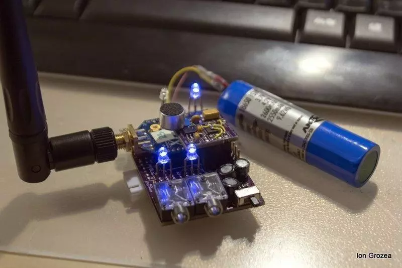
Wireless light sensor - 10000 gain in 2 steps using LMV722 Operational Ampifier and AD5235 Digital potentiometer to control the sensitivity
It is used to sense small changes in light level and can trigger the camera above or below a predefined threshold. Can be used to detect lightnings
by averaging the ambient light level.
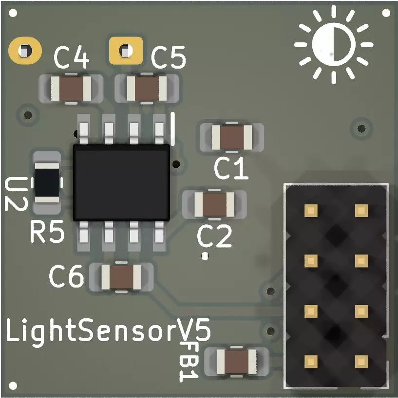
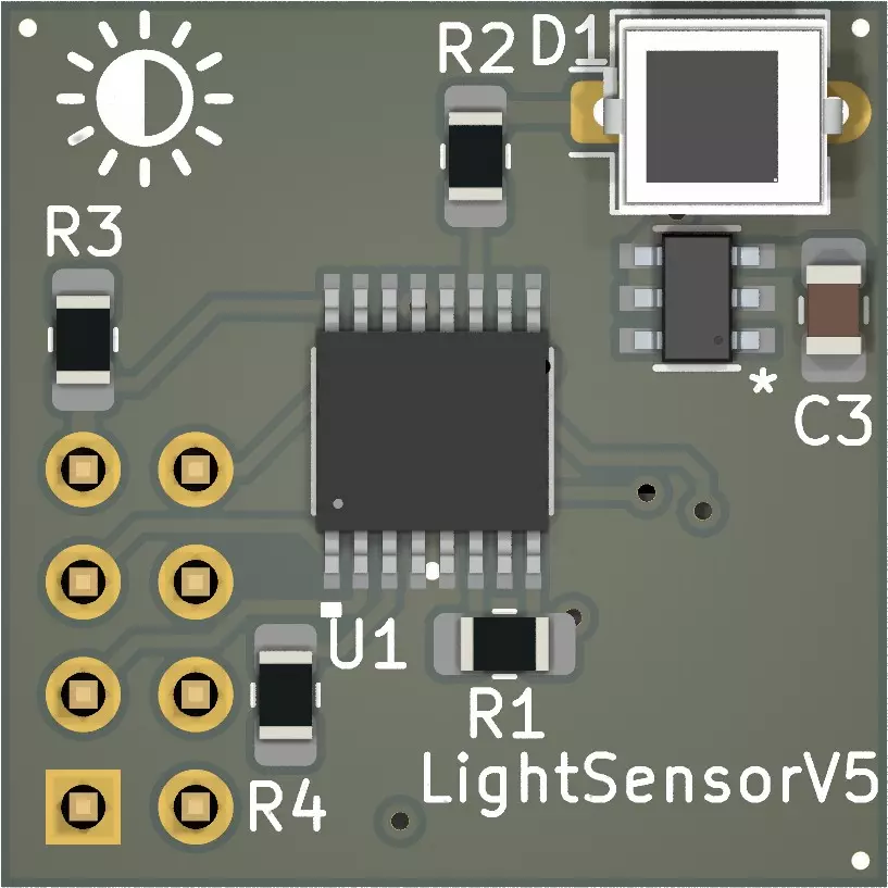
Both sensors include a high speed photo-gate and they can be programmed to execute different functions.
The main controller is shown below
1. Inside view
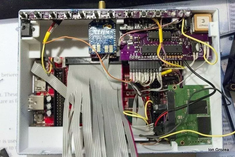
2. Side view
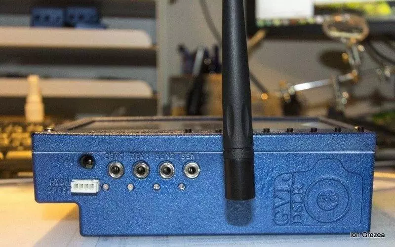
3. Main application under development for Android OS

In order for this to work proper don't forget to add 2.2kOhm pull up resistors on READY and SDO pins
Connections
CLK - CLK
SDI - MOSI
SDO - MISO
CS - PB1 - pin 9
RDY - A3
Measure the resistance on terminals B1 and B2, A1 and A2 are going in the opposite way
Read the data sheet for timings and settings.
Tested on ATMega 328p @24MHz - to have a clue about the SPI speed
Code:
//GROZEA Ion
//www.grozeaion.com
//Open Source, licensed under a Creative Commons Attribution-NonCommercial 3.0 License (http://creativecommons.org/licenses/by-nc/3.0/)
//License Agreement
//
//Copyright (c) 2015 GROZEA Ion (www.grozeaion.com)
//All rights reserved.
//
//Redistribution and use in source and binary forms, with or without modification,
//are permitted provided that the following conditions are met:
//
//* Redistributions of source code must retain the above copyright notice, this
//  list of conditions and the following disclaimer.
//
//* Redistributions in binary form must reproduce the above copyright notice, this
//  list of conditions and the following disclaimer in the documentation and/or
//  other materials provided with the distribution.
//
//* The name of the copyright holder may not be used to endorse or promote
//  products derived from this software without specific prior written permission.
//
//THIS SOFTWARE IS PROVIDED BY THE COPYRIGHT HOLDER "AS IS" AND ANY EXPRESS OR
//IMPLIED WARRANTIES, INCLUDING, BUT NOT LIMITED TO, THE IMPLIED WARRANTIES OF
//MERCHANTABILITY AND FITNESS FOR A PARTICULAR PURPOSE ARE DISCLAIMED. IN NO EVENT
//SHALL THE COPYRIGHT OWNER BE LIABLE FOR ANY DIRECT, INDIRECT, INCIDENTAL,
//SPECIAL, EXEMPLARY, OR CONSEQUENTIAL DAMAGES (INCLUDING, BUT NOT LIMITED TO,
//PROCUREMENT OF SUBSTITUTE GOODS OR SERVICES; LOSS OF USE, DATA, OR PROFITS;
//OR BUSINESS INTERRUPTION) HOWEVER CAUSED AND ON ANY THEORY OF LIABILITY, WHETHER
//IN CONTRACT, STRICT LIABILITY, OR TORT (INCLUDING NEGLIGENCE OR OTHERWISE)
//ARISING IN ANY WAY OUT OF THE USE OF THIS SOFTWARE, EVEN IF ADVISED OF THE
//POSSIBILITY OF SUCH DAMAGE.
#define CS_ON PORTB |=(1<<1)
#define CSOFF PORTB &= ~(1<<1)
#define CMD_NOP 0x00 //0- Do nothing

void setup() {
	Serial.begin(9600);
	//Setup SPI and start it
	DDRB |= B0101110;//Set digital pin 10SS, 11MOSI and 13SCK as output
	//See https://sites.google.com/site/qeewiki/books/avr-guide/spi for setting the SPI
	SPSR = B00000000;//In my case Clock / 2 = 12Mhz is not working so i use Clock / 4
	SPCR = B01010000;
	DDRC &= ~(1<<0); //A3 Input - Read Status
	PORTC |= B00000111;// Turn on 20K pullup on analog 0, 1, 2
	CS_ON;
	delay(15);
	Serial.print("Tolerance : "); Serial.print(getTolerance());Serial.println("%");
	setWiper(0, 999);
	setWiper(1, 333);
	Serial.print("W1 Value : "); Serial.println(getWiper(0));
	Serial.print("W2 Value : "); Serial.println(getWiper(1));
	stepUp1(0);
	stepUp1(1);
	Serial.print("Increase W0 with 1 : "); Serial.println(getWiper(0));
	Serial.print("Increase W1 with 1 : "); Serial.println(getWiper(1));
	stepUp1(0);
	repeatCMD();
	stepUp1(1);
	repeatCMD();
	Serial.print("W1 after repeat : "); Serial.println(getWiper(0));
	Serial.print("W2 after repeat : "); Serial.println(getWiper(1));
	stepDown6Db(0);
	stepDown6Db(1);
	Serial.print("Decrease W0 with 6dB : "); Serial.println(getWiper(0));
	Serial.print("Decrease W1 with 6dB : "); Serial.println(getWiper(1));
	stepDownAll6Db();
	Serial.print("W1 after stepDownAll6Db: "); Serial.println(getWiper(0));
	Serial.print("W2 after stepDownAll6Db: "); Serial.println(getWiper(1));
	stepUpAll6Db();
	Serial.print("W1 after stepUpAll6Db: "); Serial.println(getWiper(0));
	Serial.print("W2 after stepUpAll6Db: "); Serial.println(getWiper(1));
	stepUp1All();
	Serial.print("W1 after stepUp1All: "); Serial.println(getWiper(0));
	Serial.print("W2 after stepUp1All: "); Serial.println(getWiper(1));
	stepDown1All();
	Serial.print("W1 after stepDown1All: "); Serial.println(getWiper(0));
	Serial.print("W2 after stepDown1All: "); Serial.println(getWiper(1));
	SPCR &= ~_BV(SPE);//End SPI}
}

void loop(){
}

//1 - Restore EEMEM (A0) contents to RDAC (A0) register. See Table 16.
void storeEEMEM2RDAC(uint8_t w){
	transferData(0x10 + w,  CMD_NOP);
}
//2 - Store wiper setting. Store RDAC (A0) setting to EEMEM (A0). See Table 15. - Use a delay of 50ms!!!
void storeRDAC2EEMEM(uint8_t w){
	transferData(0x20 + w,  CMD_NOP);
}
//3 - Store contents of Serial Register Data Byte 0 and Serial Register Data Bytes 1 (total 16 bits) to EEMEM (ADDR). See Table 18.- Use a delay of 50ms!!!/RDAC1 is 0, RDAC2 is 1, User1 is 2....User13 is 14
void setEEMEM(uint8_t w, uint16_t v){
	transferData(0x30 + w, v);
}
//4 - Decrement by 6 dB. Right-shift contents of RDAC (A0) register, stop at all 0s.
void stepDown6Db(uint8_t w){
	transferData(0x40 + w,  CMD_NOP);
}
//5 - Decrement all by 6 dB. Right-shift contents of all RDAC registers, stop at all 0s.
void stepDownAll6Db(){
	transferData(0x50 , CMD_NOP);
}
//6 - Decrement contents of RDAC (A0) by 1, stop at all 0s.
void stepDown1(uint8_t w){
	transferData(0x60 + w, CMD_NOP);
}
//7 - Decrement contents of all RDAC registers by 1, stop at all 0s.
void stepDown1All(){
	transferData(0x70, CMD_NOP);
}
//8 - Reset. Refresh all RDACs with their corresponding EEMEM previously stored values. - Use a delay of 30us!!!
void refreshAllRDAC(){
	transferData(0x80, CMD_NOP);
}
//9 - Read contents of EEMEM (ADDR) from SDO output in the next frame. See Table 19. - Use a delay of 30us!!!
uint16_t getEEMEM(uint8_t w){
	transferData(0x90 + w, CMD_NOP);
	delayMicroseconds(30);
	return transferData(CMD_NOP, CMD_NOP);
}
//10 - Read RDAC wiper setting from SDO output in the next frame. See Table 20. - Use a delay of 30us!!!
uint16_t getWiper(uint8_t w){
	transferData(0xA0 + w, CMD_NOP);
	delayMicroseconds(30);
	return transferData(CMD_NOP, CMD_NOP);
}
//11 - Write contents of Serial Register Data Byte 0 and Serial Register Data Byte 1 (total 10 bits) to RDAC (A0). See Table 14.
void setWiper(uint8_t w, uint16_t v){
	transferData(0xB0 + w, v);
}
//12 - Increment by 6 dB: Left-shift contents of RDAC (A0),stop at all 1s. See Table 17.
void stepUp6Db(uint8_t w){
	transferData(0xC0, CMD_NOP);
}
//13 - Increment all by 6 dB. Left-shift contents of all RDAC registers, stop at all 1s.
void stepUpAll6Db(){
	transferData(0xD0, CMD_NOP);
}
//14 - Increment contents of RDAC (A0) by 1, stop at all 1s. See Table 15.
void stepUp1(uint8_t w){
	transferData(0xE0 + w, CMD_NOP);
}
//15 - Increment contents of all RDAC registers by 1, stop at all 1s.
void stepUp1All(){
	transferData(0xF0, CMD_NOP);
}
//16 - See page 21 in manual Another subtle feature of the AD5235 is that a subsequent CS strobe, without clock and data, repeats a previous command
void repeatCMD(){
	CSOFF;
	CS_ON;
}

float getTolerance(){
	float tol = getEEMEM(15);
	uint8_t b_1 = ((uint16_t)tol >> 8);
	uint8_t b_0 = ((uint16_t)tol & 0xFF);
	if(b_1 > 127) //check if first bit in b_1 is 1
		b_1 -= 128;
	else
		b_1 -= b_1;
	for(uint8_t p = 0; p < 8; p++){
		if((b_0 >> p) & 1)//check if but in position p is 1
		{
			tol = b_1 + ((float)b_0)/ ((float)(1 << (8 - p)));//add the decimal part of the tolerance
			break;
		}
	}
	return tol;
}

uint16_t transferData(uint8_t cmd, uint16_t val){
	CSOFF;
	uint8_t bytes[2];
	bytes[0] = cmd;
	bytes[1] = val >> 8;
	bytes[2] = val & 0xFF;
	for(uint8_t i =0; i < 3; i++){
		SPDR = bytes[i];// send the data
		while(!(SPSR & (1<<SPIF)))// wait until transmission is complete
		;
		bytes[i] = SPDR;
	}
	CS_ON;
	return (uint16_t)(bytes[1] << 8) + bytes[2];
}