Custom ESP8266 with all pins exposed
Please read Liability Disclaimer and License Agreement CAREFULLY
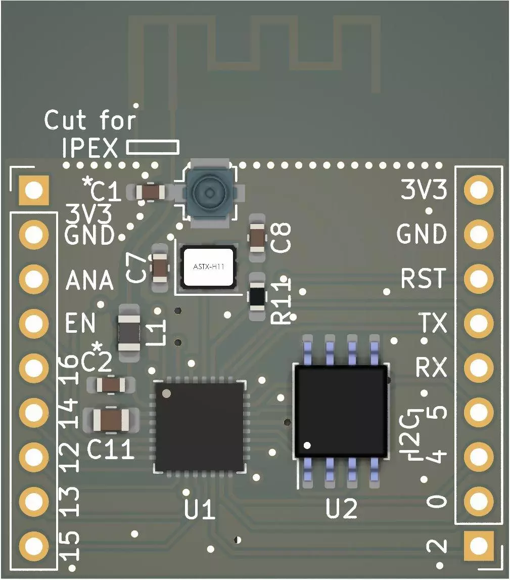
ESP8266 or ESP-01 is a great tiny board that will be enough for most of your projects but many of the pic of the ESP8266EX will not be use and it hard to connect to them.
If you have to get access to all ESP8266 pins and you have the soldering tools and skills you can order the PCB I have created for this approach.


The whole KiCAD project can be downloaded here.
The following pins have 12k pull up resistors: EN-R4, RST-R7, IO0-R4, IO2-R6, IO4-R9 and IO5-R10.
If you do not intend to use I2C or you have the I2C pull up resistors in a different place you can remove R9 and R10.
Pin IO15 is pulled down using R8 12k resistor.

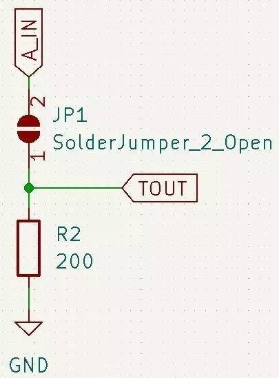
ANA pin is used for analog readings of maximum 1V. I have integrated on the PCB a voltage divider with "R1" ![]() and R2 where "R1" is actually a jumper. If the voltage divider is implemented in a different place R2 can be skipped and R1 must be closed.
and R2 where "R1" is actually a jumper. If the voltage divider is implemented in a different place R2 can be skipped and R1 must be closed.
You will need to calculate yourself the "R1" and R2 values, note that R2 is connected to GND.

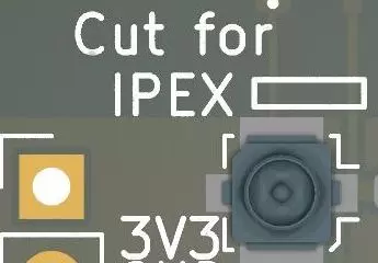
By default the antenna is integrated on the PCB but there is place to add an external antenna using the IPEX connector. In this case to not forget to cut the traces to PCB antenna.

C1 and C2 can be ignored when populating the PCB with parts, after testing you can add or remove them depending of the Wi-Fi signal strength.
At JLCPCB a set of 5 PCBs is 2USD, so I believe that it will be cheaper to move the parts from the original PCB to the custom one and get access to all ESP8266EX pins.
Comments powered by CComment