Mooz 2 - CNC on steroids
Please read Liability Disclaimer and License Agreement CAREFULLY
Intoduction
The CNC head used on Mooz 2 is OK to be used for milling operations where you remove a layer with a thickness of 0.2mm to 0.5mm at about 90mm/s federate
with tools up to 4mm in diameter.
With the above setting you will get a lot of noise due to vibrations, most of them are due to the poor design and fixation of the CNC head (bearings and weak
fixation are the primary cause).
In order to overcome the issues above i decided that i will give a try to the 500W air cooled spindle found on Aliexpress at a good discount price.
The speed of the spindle above can be controlled using a voltage from 0V to 10V, this feature might be used to control the spindle speed using the Mooz 2
PCB from the CNC head.
So first thing is to try to understand how the CNC head electronics are working.
Part 1 - Mooz 2 CNC head electronics
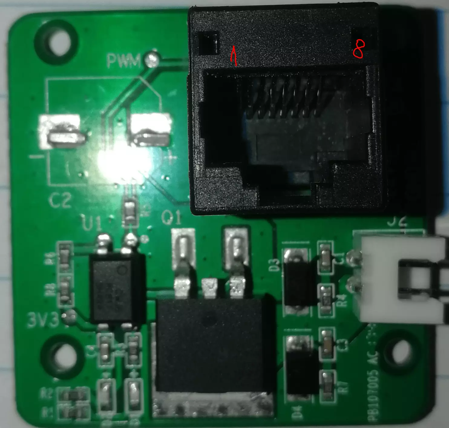
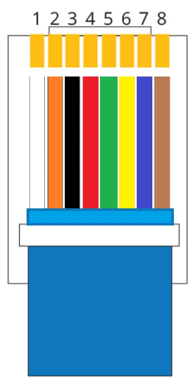
The connector used on cable to connect each module to the printer is RJ4
The schematic for the CNC head PCB
This is reversed engineered, so you need to double check before using it

Below is a chart with the Voltages as function of PWM values (8bits)

Notes:
1. My guess is that resistor R9 with a value of 254kOhm is used to identify the module connected to the printer.
2. On the LASER module we have a resistor connected to the same 7-8 pins with a value of 220kOhm.
3. Pins:
1 - 12V
2 - GND
3 - HEAT (used on 3D printer module)
4 - PWM / FAN (used on 3D printer module)
5 - ???
6 - PWM (used on 3D printer module)
7 - ID1 / ADC (used on 3D printer module)
8 - ID2 / ???
Pins 1, 2 are used for power on all modules, pins 4, 7 and 8 are the same on CNC and LASER.
Part 2 - Upgrading to 500W spindle
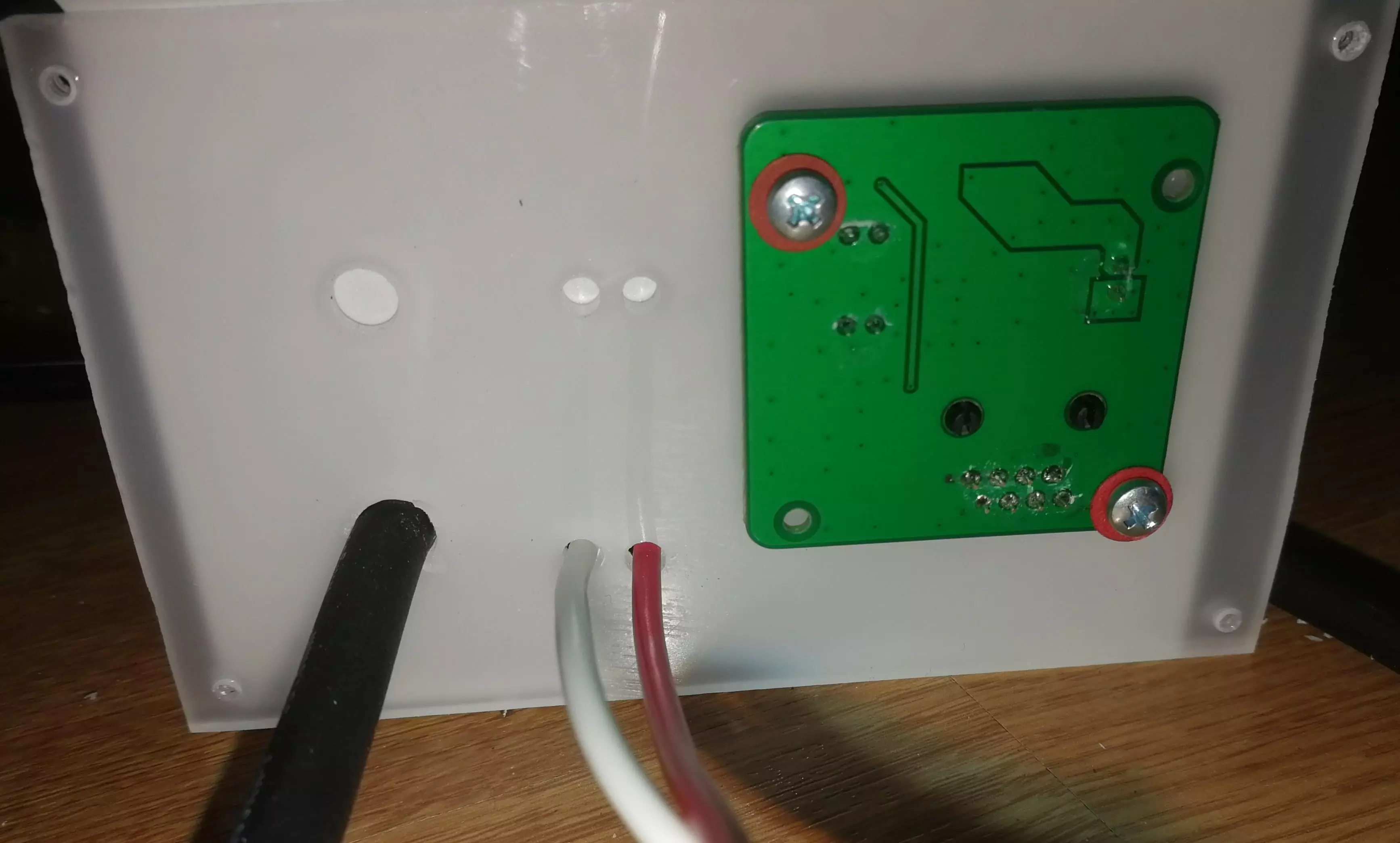
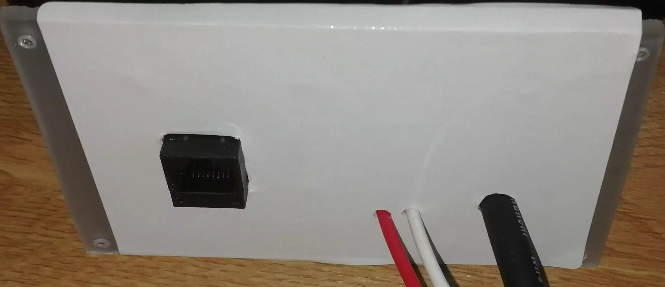
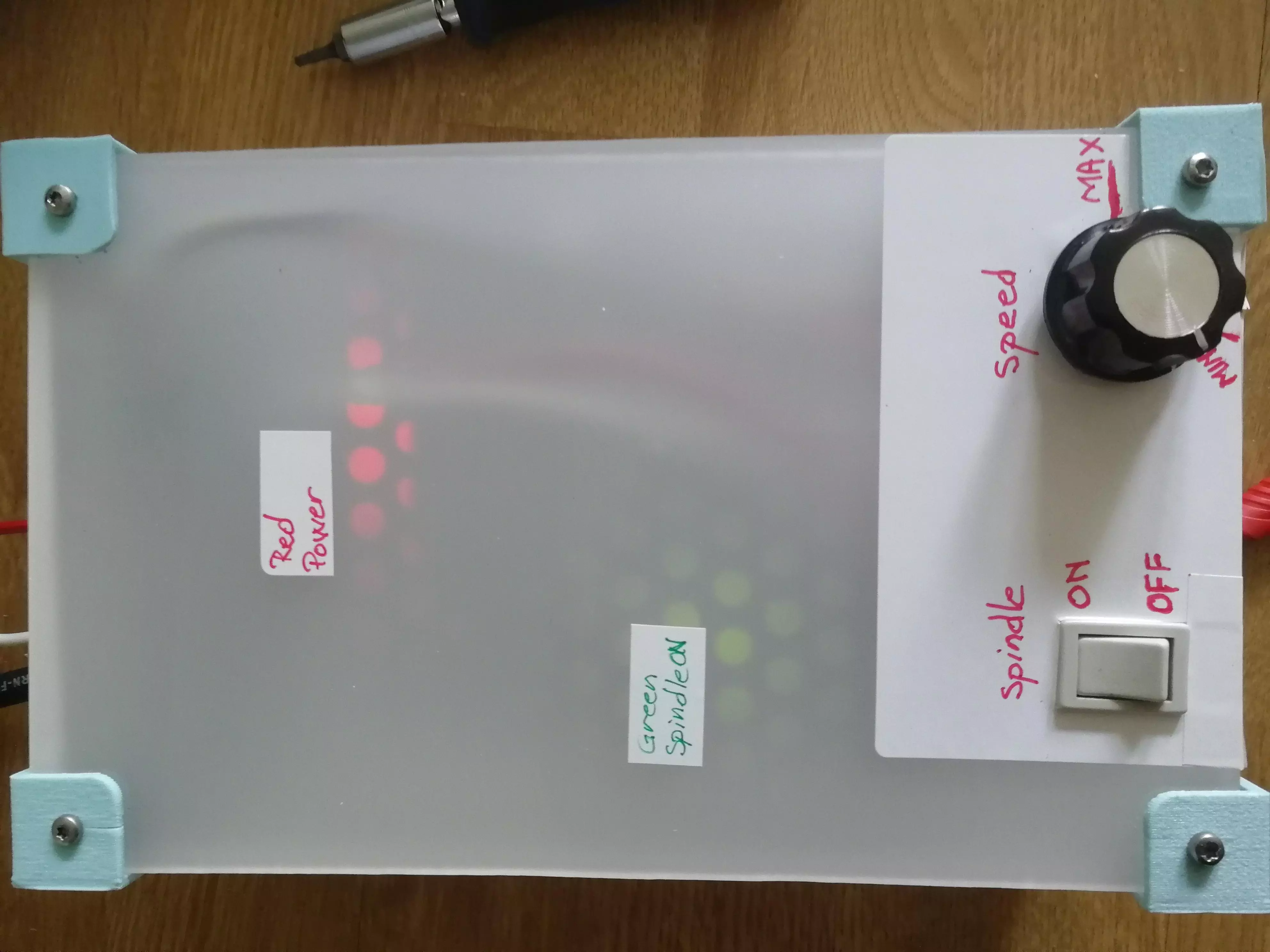
Using some acrylic leftovers i had from a previews project I tried to make with what i had an enclosure for the electronics and power supply.
Below is a series of pictures with the build.
1. From left to right we have speed control RED, YELLOW, BLACK; Spindle switch RED, WHITE; Spindle connection RED, WHITE
Power chord BLUE, BROWN and GREEN/YELLOW(This is connected to the power supply enclosure.
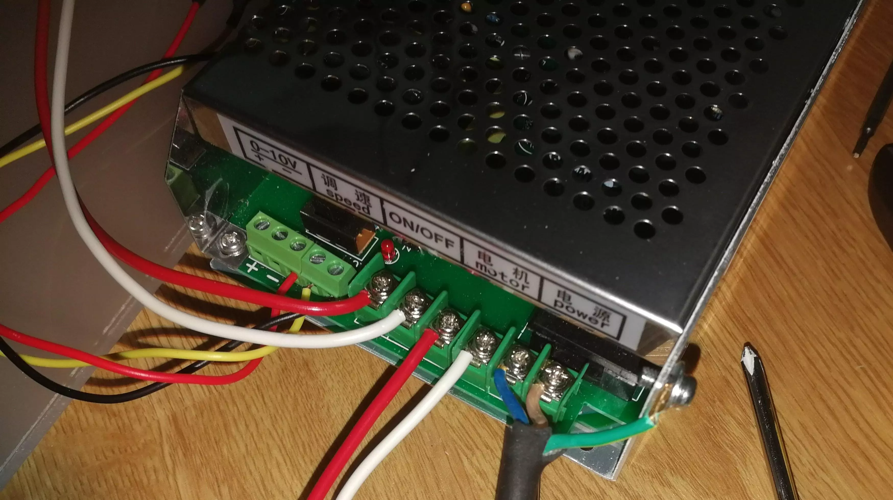
2. Assembly pictures
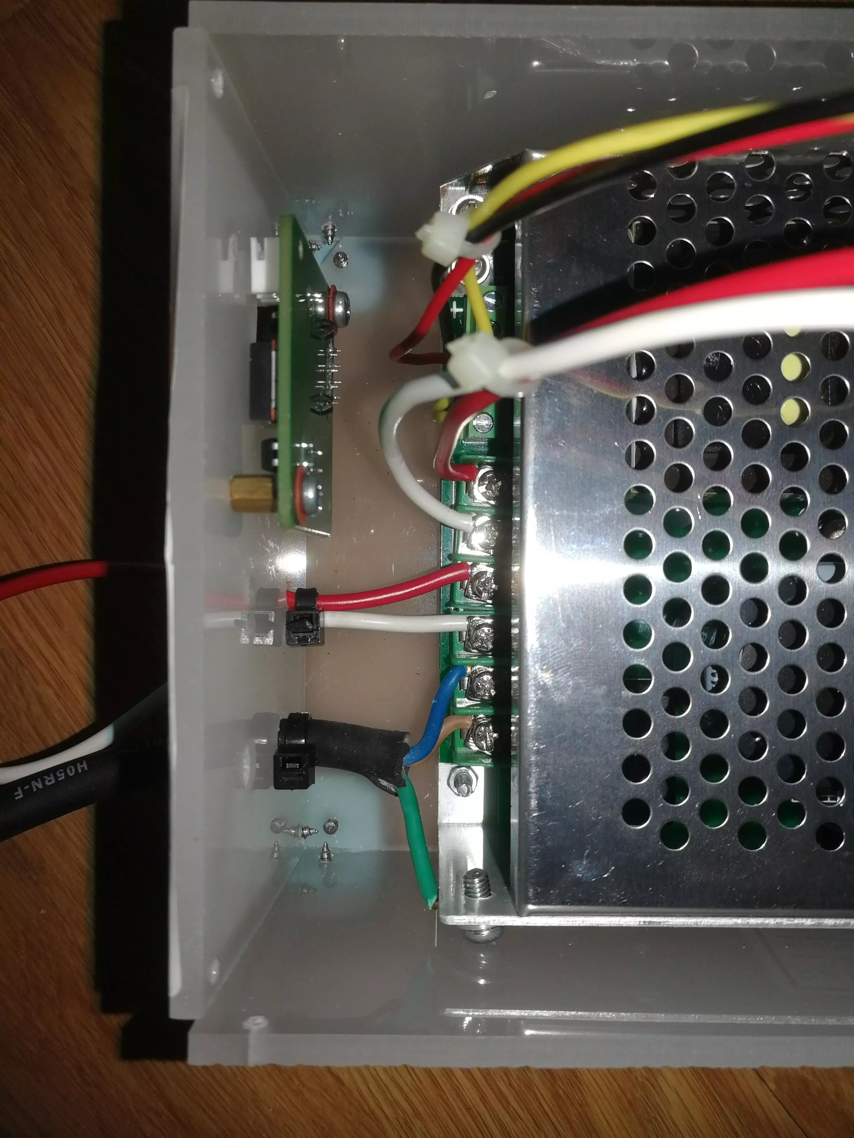
3. Final assembly
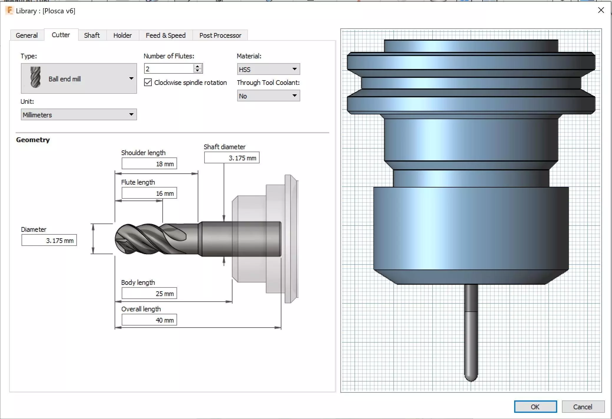
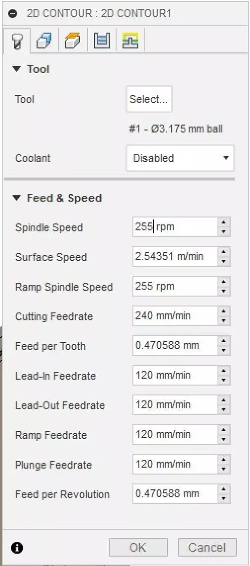
4. Fusion 360 setup
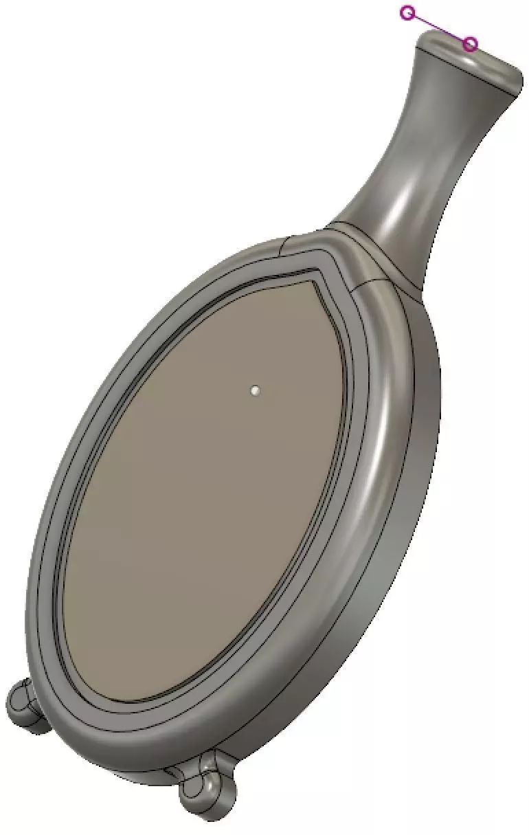
Because Create g-code for Mooz 2 using Fusion 360 seems that is not clear on how to create a tool in Fusion 360
I have added the images below hoping that will make this topic clear.
5. First use video
Right click on the video to get the menu from where you can save the video
Your comments or ideas are welcomed.
Comments powered by CComment